DSA Maximum Flow
The Maximum Flow Problem
The goal of the Maximum Flow issue is to determine the greatest flow from one location on a directed graph to another.
To be more precise, the flow originates at a source vertex. s ultimately arriving at a sink vertex t, and every edge in the graph has a defined flow and capacity, where the latter is the edge’s maximum possible flow.
==== EXAMPLE MUKAVU ====
Determining the maximum flow has many benefits.
- to design city roads in a way that prevents future traffic bottlenecks.
- to evaluate the impact of cutting a network cable, an electrical wire, or a water pipe.
- To increase traffic, data traffic, or water flow, for example, one must determine where in the flow network increasing capacity will result in the highest possible flow.
Terminology And Concepts
Generally speaking, a directed graph having a flow through it is referred to as a flow network.
The ability c of an edge indicates the maximum amount of flow that can pass through it.
Additionally, each edge has a flow value that indicates the amount of current flowing through it.
The border in the picture above v 1→v2., starting at the vertex v1. to the vertex v2.
has a flow and capacity of 0/7, meaning that there is no flow and a capacity of 7. Thus, it is possible to increase the flow in this edge to 7, but not higher.
An uncomplicated flow network contains a single source vertex. s where one sink vertex and the flow exit t where the flow enters. There is merely flow moving through the other vertices.
For any vertex other from sadditionally tthe same quantity of flow that enters a vertex must likewise exit it due to the conservation of flow.
By sending more and more flow via the edges in the flow network until the edges’ capacity is reached to the point where no more flow can be sent through, algorithms like Ford-Fulkerson or Edmonds-Karp are able to determine the maximum flow. An augmented path is one where more flow can be transmitted through.
Relative to the Ford-Fulkerson and Edmonds-Karp algorithms, a residual network is used in their implementation. The next pages will provide a more thorough explanation of this.
Each edge in the residual network has its residual capabilities configured, whereby an edge’s residual capacity is its capacity less the flow. Thus, an increase in flow at an edge results in a corresponding decrease in residual capacity.
There is a reversed edge that points in the opposite direction of the original edge for every edge in the residual network. The flow of the original edge is the remaining capacity of a reversed edge. In order to transmit flow back on an edge as part of the maximum flow algorithms, reversed edges are crucial.
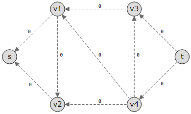
The graph from the simulation at the top of this page has its edges reversed, as shown in the image below. Since there was no flow in the graph to begin with, each reversed edge points in the opposite direction, and the residual capacity for the reversed edges are 0.

It can be challenging to comprehend some of these ideas, such as the residual network and the reversed edge. For this reason, the following two pages provide a more thorough explanation of these ideas along with examples.
The amount of flow that can be sent through the flow network overall is determined when the maximum flow is located.
Multiple Source and Sink Vertices
One source vertex and one sink vertex are expected to be able to identify the greatest flow according to the Ford-Fulkerson and Edmonds-Karp algorithms.
To determine the maximum flow, the graph should be adjusted if there are many source or sink vertices.
Create an additional super-source vertex if the graph has more than one source vertex, and an additional super-sink vertex if the graph has more than one sink vertex in order to change it such that the Ford-Fulkerson or Edmonds-Karp method can be applied to it.
Create edges with limitless capacity from the super-source vertex to the original source vertices. And similarly, establish edges with infinite capacity from the sink vertices to the super-sink vertex.
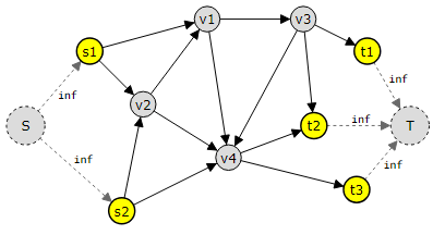
The image below shows such a graph with two sources s1 and s2, and three sinks t1, t2, and t3.
To run Ford-Fulkerson or Edmonds-Karp on this graph, a super source is created with edges with infinite capacities to the original source nodes, and a super sink Tis created with edges with infinite capacities to it from the original sinks.

By moving from the super source S to the super sink, the Ford-Fulkerson or Edmonds-Karp algorithm may now determine the maximum flow in a graph with numerous source and sink vertices. T..
The Max-flow Min-cut Theorem
In order to comprehend the implications of this theorem, we must first define a cut.
We construct two sets of vertices: “S,” which contains only the source vertex, and “T,” which has all of the other vertices, including the sink vertex.
As long as we do not include the sink vertex, we can now opt to expand set S by adding more nearby vertices, starting from the source vertex and going as far as we choose.
Since every vertex belongs to either set S or set T, expanding set S will cause set T to shrink.
There is a “cut” between the sets in such a configuration, where any vertex can belong to either set S or set T. All of the edges that extend from set S to set T make up the cut.
The capacity of the cut, or the total feasible flow from source to sink in this cut, is obtained by adding all the capacities from edges flowing from set S to set T.
The bottleneck will be the minimum cut, or the cut we can make with the lowest possible overall capacity.
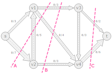
Three distinct cuts have been made to the graph from the simulation at the top of this page in the image below.

Cut A: This cut has vertices s and v1 in set S, and the other vertices are in set T. The total capacity of the edges leaving set S in this cut, from sink to source, is 3+4+7=14. We are not adding the capacity from edge
v2→v1, because this edge goes in the opposite direction, from sink to source. So the maximum possible flow across cut A is 14.
Cut B: The maximum possible flow is 3+4+3=10 across cut B.
Cut C: A maximum flow of 2+6=8 can pass through cut C. There wouldn’t be a cut in the graph with a lower total capacity if we looked at every other cut. The bare minimal cut is this. Have you used the simulation to find this page’s maximum flow? The max-flow min-cut theorem precisely states that 8 is the maximum flow, as you also know.
The max-flow min-cut theorem states that since the value of the minimum cut and the maximum flow are equal, determining the minimum cut on a graph is equivalent to determining the maximum flow.
Practical Implications of The Max-flow Min-cut Theorem
Utilizing an algorithm such as Ford-Fulkerson to find a graph’s maximum flow also aids in determining the location of the minimum cut: Where the edges are fully packed will be the least cut.
Since the bottleneck will be located at the lowest cut, we now know which edges in the graph need to be changed in order to raise the overall flow if we wish to increase flow above the maximum limit, which is frequently the case in real-world scenarios.
In numerous circumstances, modifying the minimum cut’s margins to permit greater flow can be quite helpful.
- City planners now know where to add more lanes, where to divert traffic, and where to best utilize traffic signals, all of which contribute to improved traffic flow.
- A larger production output in manufacturing can be attained, for example, by reallocating resources or improving equipment where the bottleneck is located.
- When a supply chain is aware of its bottleneck, it can be modified to transport goods from warehouses to customers more efficiently by altering routes or adding capacity when needed.
Therefore, determining the minimal cut utilizing maximum flow methods aids in our understanding of where changes to the system can be made to enable even higher throughput.
The Maximum Flow Problem Described Mathematically
The Maximum Flow Problem Described Mathematically
The maximum flow issue is a subset of mathematical optimization, which is a topic in mathematics as well as computer science.
The maximum flow problem is explained mathematically below, in case you’d like a more in-depth understanding of this.
All edges (E) in the graph, going from a vertex (u) to a vertex (v), have a flow (f) that is less than, or equal to, the capacity (c) of that edge:
∀(u,v)∈E:f(u,v)≤c(u,v)
This essentially indicates that an edge’s capacity determines how much flow it can accommodate.
Furthermore, for every edge (E), a single-directional flow from You to v is equivalent to having a negative flow going the other way, from v to You:
∀(u,v)∈E:f(u,v)=−f(v,u)
And the expression below states that conservation of flow is kept for all vertices (u) except for the source vertex (s) and for the sink vertex (t):
∀u∈V∖{s,t}⇒∑w∈Vf(u,w)=0
This simply indicates that, with the exception of the source and sink vertices, the amount of flow entering a vertex equals the amount of flow exiting that vertex.
Finally, all flow is released from the source vertex to arrive at the sink vertex. t:
∑(s,u)∈Ef(s,u)=∑(v,t)∈Ef(v,t)
According to the aforementioned equation, summing all of the flow that exits the source vertex and all of the flow that enters the sink vertex will equal the total.
